What the thin lens formula describes
For a thin lens in the paraxial approximation, object distance dₒ, image distance dᵢ and focal length f satisfy 1/f = 1/dₒ + 1/dᵢ. Distances must use the same unit. The equation locates the ideal image; magnification then predicts its size and orientation. A real lens has thickness and optical imperfections, so a physical image may not have a perfectly sharp mathematical point.
Use one sign convention throughout. Here a real object has positive dₒ, a converging lens has positive f and a diverging lens has negative f. Positive dᵢ means a real image on the side opposite the object; negative dᵢ means a virtual image on the object’s side.
Convex lens example: a real image on a screen
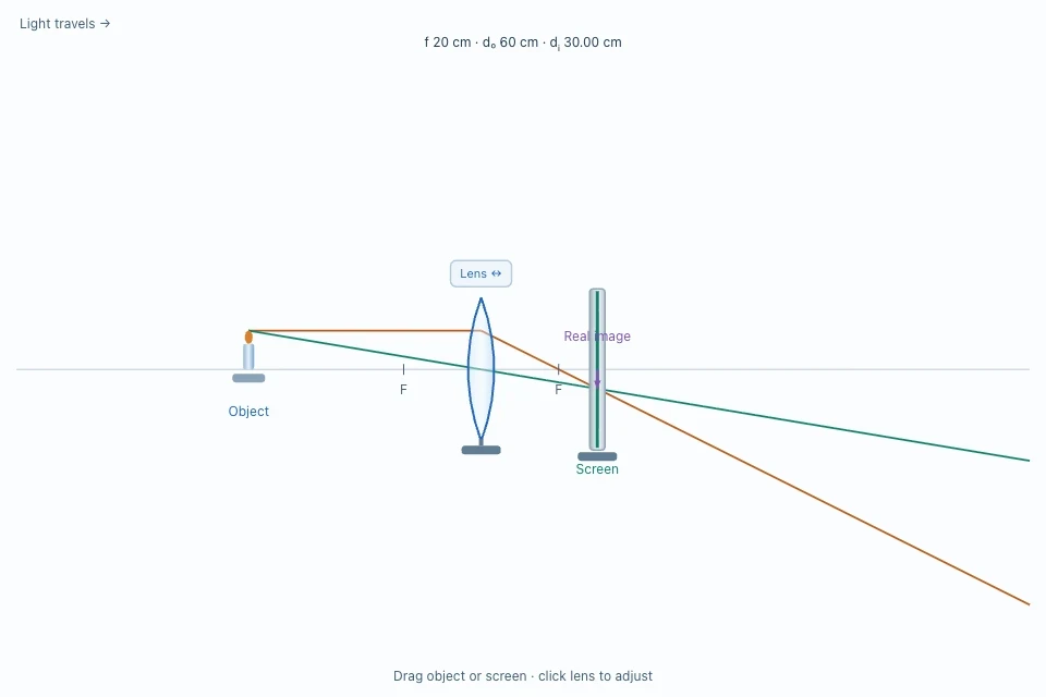
Place an object 30 cm from a converging lens with focal length +10 cm. Then 1/dᵢ = 1/10 − 1/30 = 1/15 cm⁻¹, so dᵢ = +15 cm. The positive result puts the real image on the other side of the lens, where a screen can intercept the converging light rays.
Magnification is m = hᵢ/hₒ = −dᵢ/dₒ = −15/30 = −0.5. The image is inverted and half the object’s height. If the object is moved closer while remaining beyond the focal point, the screen must move farther from the lens to regain focus.
Concave lens example: a virtual image on the object’s side
Keep dₒ = +30 cm but replace the lens with a diverging lens of focal length −10 cm. Now 1/dᵢ = −1/10 − 1/30 = −2/15 cm⁻¹, giving dᵢ = −7.5 cm. The negative image distance places the image on the same side of the lens as the object.
Magnification is m = −(−7.5)/30 = +0.25. The virtual image is upright and one quarter of the object’s height. A screen on the opposite side cannot capture that image, because the outgoing rays do not actually meet at the virtual image position. An observer looking through the lens can see it along the backward extensions of those rays.
What happens inside the focal length?
A converging lens can also form a virtual image. If an object is placed closer to the lens than its positive focal length, the formula gives negative dᵢ and positive magnification. The image appears upright and enlarged on the object’s side, as with a simple magnifier.
At exactly the focal point in the ideal thin-lens model, outgoing rays are parallel and the image distance tends toward infinity. A finite screen position cannot bring that ideal image into focus. Be cautious about describing a screen image in this limiting case.
Draw rays before trusting the signs
A ray parallel to the principal axis of a converging lens passes through the far focal point; a ray through the lens centre continues approximately straight in the thin-lens sketch. For a diverging lens, a parallel incident ray leaves as though it came from the near focal point. Extend outgoing rays backward with dashed lines to locate a virtual image.
A sign error becomes easier to spot when the drawing and arithmetic disagree. A negative dᵢ should not send a real screen to the far side. A negative magnification should show inversion. Keep the same reference point and convention for every trial.
Investigate real and virtual images on the optical bench
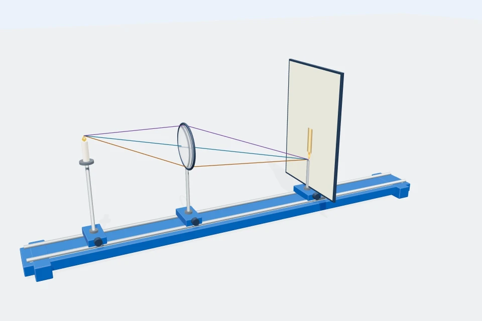
In the 3D optical bench, choose a convex lens and move the candle and screen along the rail. Predict the image plane from the thin lens formula, then use Focus screen to check it. Change only the candle distance and repeat. The 2D ray diagram makes the construction lines easier to compare.
Next select the concave lens. The interface offers Inspect virtual image on the object’s side when that view is within range. The dashed lines represent backward extensions, not light travelling back through the lens. Compare the predicted negative image distance with the model’s displayed value; do not try to focus a virtual image on the screen.
Sources and further reading
- OpenStax University Physics: thin lenses, sign conventions and magnification
- OpenStax College Physics: image formation by converging and diverging lenses
Found an error or a confusing explanation? Send a science correction.