What Snell’s law tells you
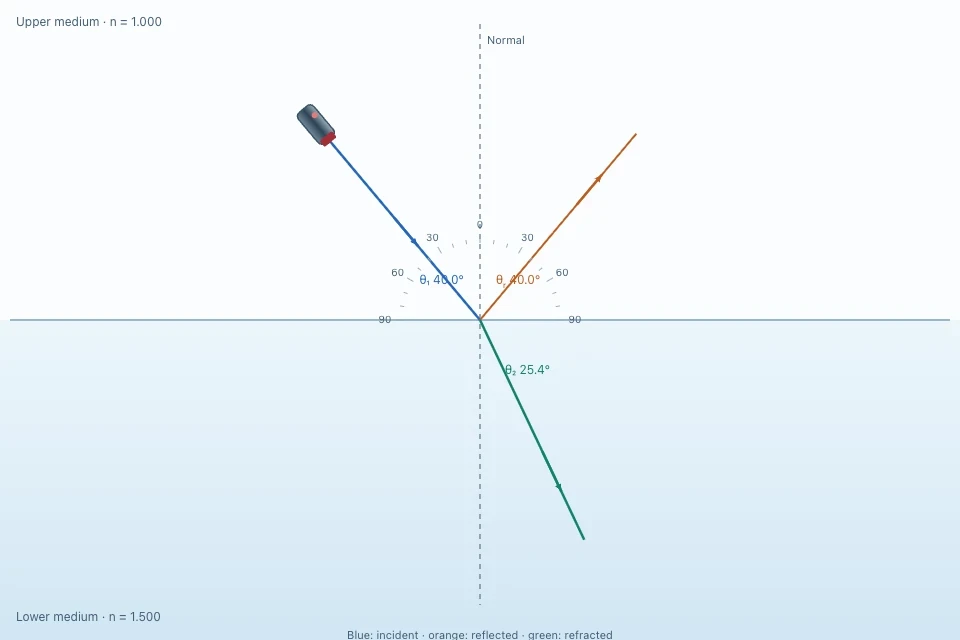
Snell’s law relates a ray’s angle before and after it crosses a boundary: n₁sinθ₁ = n₂sinθ₂. The indices n₁ and n₂ describe the two media; θ₁ and θ₂ are measured from the normal, a line perpendicular to the boundary. The incident and refracted rays lie on opposite sides of that boundary. Draw the normal first, then label the medium each angle belongs to.
In an ideal transparent medium, refractive index n = c/v, where c is light speed in vacuum and v is its speed in that medium. If light enters a medium with a larger n, its speed decreases and its ray bends toward the normal. If it enters a smaller n, it bends away. At normal incidence, θ₁ = θ₂ = 0°, so the ray does not change direction.
Find the refracted angle step by step
Rearrange the equation as sinθ₂ = (n₁/n₂)sinθ₁, then take inverse sine. For light going from air (n₁ = 1.000) into teaching glass (n₂ = 1.500) at 40.0° to the normal, sinθ₂ = sin40.0°/1.500 ≈ 0.4285. Therefore θ₂ ≈ 25.4°. It is smaller than 40.0°, as expected when entering the higher-index medium.
Check that your calculator is in degrees and that the answer is measured to the normal, not to the surface. If you have an angle measured to the surface, subtract it from 90° before using Snell’s law. The values 1.000 and 1.500 are simplified teaching inputs, not exact indices for every wavelength and material.
What changes at the boundary—and what does not
The frequency of the light stays the same as it crosses a stationary boundary. Its speed and wavelength change together: v = c/n and λmedium = λvacuum/n for the ideal non-dispersive treatment. A smaller wavelength in glass does not mean the light source changed frequency.
A portion of light can also reflect at the boundary. The reflected angle equals the incident angle, both measured from the normal. A ray sketch shows directions, but does not by itself calculate how much optical power is reflected or transmitted. Labmora’s ray colour and thickness likewise identify paths, not intensity.
Critical angle and total internal reflection
Total internal reflection is possible only when light travels from a higher refractive index to a lower one. At the critical incident angle θc, the refracted ray lies along the boundary (θ₂ = 90°). Snell’s law then gives sinθc = n₂/n₁, so θc = sin⁻¹(n₂/n₁). Above θc, there is no propagating refracted ray in the lower-index medium.
For the teaching glass-to-air boundary with n₁ = 1.500 and n₂ = 1.000, θc = sin⁻¹(1/1.5) ≈ 41.8°. At 40° a transmitted ray is possible; at 50° total internal reflection occurs. Reversing the direction to air-to-glass removes this critical-angle condition because n₁ is then smaller than n₂.
Investigate the ray in Labmora
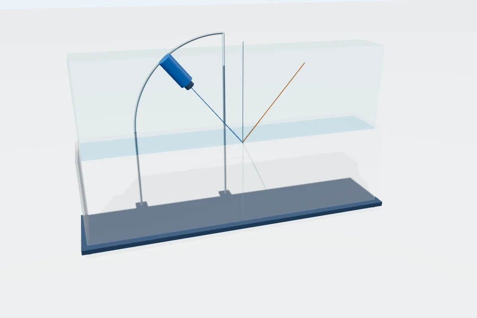
Open the 3D refraction lab. Choose “Air into glass,” set the upper and lower indices to 1.000 and 1.500, and steer the incident ray to 40.0° from the normal. Predict about 25.4° before reading the refracted-angle value. The upper and lower indices can be changed independently; keep them fixed when testing how angle alone changes the path.
Next choose “Glass into air · total reflection.” Set the angle just below, near and above 41.8°. Note when the transmitted ray grazes the boundary and when it disappears. You can drag the incident ray in the upper half of the diagram. Repeat in the 2D version if you want a flatter ray construction, then test the “Same medium · no bending” preset.
Four common mistakes to catch
First, measuring angles from the surface rather than the normal gives a plausible-looking but wrong answer. Second, swapping n₁ and n₂ can predict a ray bending the wrong way; make a quick qualitative prediction before calculating. Third, getting (n₁/n₂)sinθ₁ greater than 1 is not a calculator error. It signals total internal reflection, provided the ray is moving from higher n to lower n.
A fourth trap is to treat the index as the same for all colours in real glass. Real materials can be dispersive, so n depends on wavelength and white light may separate. The Labmora model keeps the chosen indices fixed when you change vacuum wavelength; it shows wavelength changes between media without simulating dispersion.
From a flat boundary to a lens
A curved lens has a boundary whose normal changes from point to point. Refraction at each surface explains why a lens can bring rays together or spread them apart. Snell’s law describes the direction change locally; the thin-lens formula is a separate approximation for image position in a thin, near-axis system.
Use the related thin-lens guide after tracing a single flat boundary here. It will help you keep the law governing a ray at a surface separate from the equation locating an image after passage through a lens.
Sources and further reading
- OpenStax University Physics: refraction and Snell’s law
- OpenStax University Physics: critical angle and total internal reflection
Found an error or a confusing explanation? Send a science correction.