What Ohm’s law says—and when it applies
Ohm’s law describes a component whose current is proportional to the potential difference across it while physical conditions, especially temperature, are held constant. Write V = IR, where V is voltage in volts, I is current in amperes and R is resistance in ohms. Rearrange it as I = V/R or R = V/I when the relevant quantities are known.
The voltage in this equation must be across the same component through which I flows. A 12 V supply does not necessarily place 12 V across every component in a series circuit. First identify the circuit arrangement, then use the correct component voltage and current.
A simple V = IR worked example
If a 6 Ω resistor has 12 V across it, I = 12/6 = 2 A. Its electrical power is P = VI = 12 × 2 = 24 W. The same result comes from I²R = 2² × 6 = 24 W. These calculations assume the resistor maintains its stated resistance; they do not by themselves predict temperature.
An I–V graph for an ohmic resistor is a straight line through the origin when conditions remain constant. If voltage is on the vertical axis and current on the horizontal axis, the gradient is R. If current is vertical and voltage horizontal, the gradient is 1/R. Always read the axis labels before describing a slope.
Series circuit: one current, shared voltage
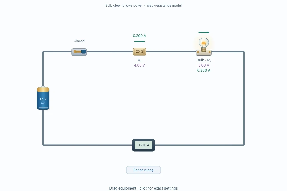
In series, the same current passes through each component and the resistances add. With an ideal 12 V battery, a 20 Ω resistor and a 40 Ω teaching bulb, total resistance is 60 Ω and current is 12/60 = 0.20 A. The voltage drops are 0.20 × 20 = 4 V and 0.20 × 40 = 8 V, which add to the 12 V supply.
The bulb’s calculated power is I²R = 0.20² × 40 = 1.6 W. This gives a useful prediction for Labmora’s fixed-resistance teaching bulb. Its glow is a qualitative response to electrical power, not a calibrated light output.
Parallel circuit: shared voltage, split current
For the same 20 Ω and 40 Ω loads connected in parallel across an ideal 12 V supply, each branch has 12 V. Their currents are 12/20 = 0.60 A and 12/40 = 0.30 A. Supply current is 0.90 A, the sum of the branch currents. Equivalent resistance is 12/0.90 ≈ 13.33 Ω.
The 40 Ω teaching bulb now has P = V²/R = 12²/40 = 3.6 W, higher than its 1.6 W in the series example. Keep the same supply voltage and component values when comparing arrangements; changing several variables at once hides the reason for the difference.
Why a real filament lamp is different
A real filament lamp heats as current increases. Its resistance therefore changes, and its I–V graph is generally curved rather than a straight line of constant gradient. Labmora deliberately treats the optional bulb as a fixed-resistance load so learners can isolate the series and parallel rules. The changing glow follows the modelled power; it does not model filament temperature in detail.
The model also uses ideal wires, battery and switch. An open switch has no conducting current. A zero-resistance closed path is an ideal short for which this simplified model does not give a finite current. Real circuits require current limiting and suitable apparatus.
Try the circuit investigation
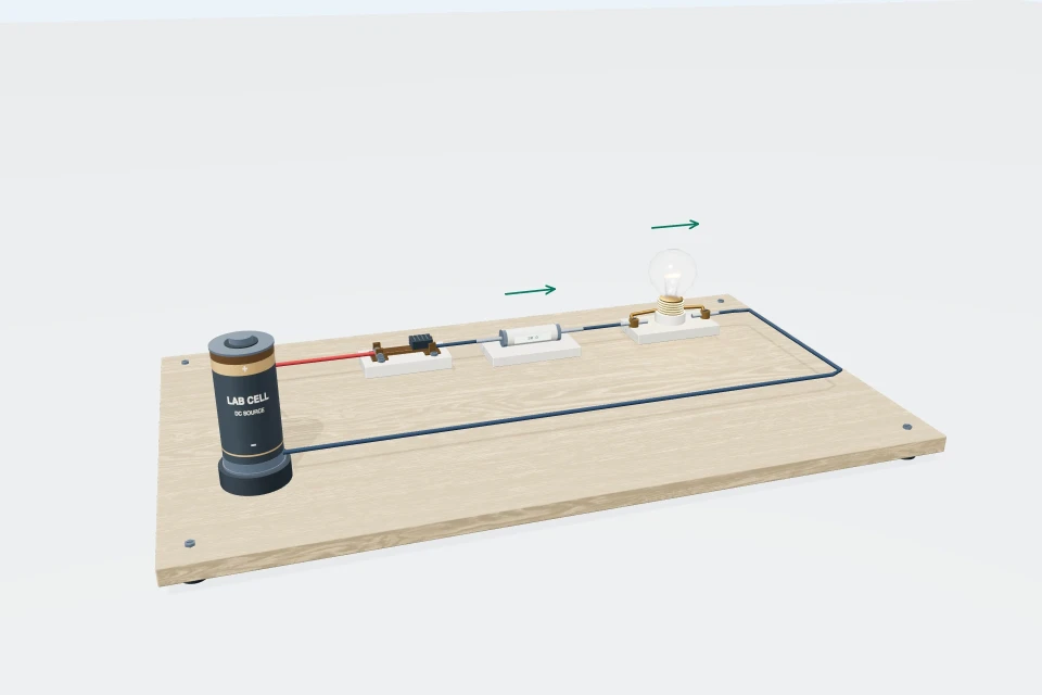
Set the 3D circuit to a 12 V battery, 20 Ω first resistor and 40 Ω fixed-resistance bulb. Close the switch and start in series. Predict current, the two voltage drops and bulb power before reading the meters. Follow the optional conventional-current arrows; they indicate the direction of positive charge flow, opposite to electron drift in metal wires.
Switch to parallel without changing the values, and compare the branch currents with the 0.60 A and 0.30 A predictions. Open the switch to check that current and glow disappear. The 2D version is useful when you want to focus on circuit topology and the I–V graph.
Sources and further reading
- OpenStax University Physics: Ohm’s law and ohmic components
- OpenStax University Physics: resistors in series and parallel
Found an error or a confusing explanation? Send a science correction.